")
")
| Design | Enclosure specifications |
Stock availability type |
Power supply | Total number of relay channels |
Relay channels load specification |
Relay channels on common bus |
Idividual relay channels |
Line voltage measurement (max. 160VDC/ 110VAC for PoE) |
Direct power supply of device from Line voltage (<160VDC/ 110VAC) |
Inputs for external sensors: TDS300 HDS300f VDS300 |
Alarm input (dry contact) |
Pulse counter inputs (for watt-hour, gas/water meters ...) |
Other | Back panel diagram | |
| 24R3S2A |  |
152x124x22mm | A | 12VDC / 1A (DC Jack) |
24 | 7A /240VAC 7A /28VDC 12A /12VDC |
24xSPDT | 3 | 2 | 24 x |
|||||
| 7R8A1RS |  |
Gray, flame retardant ABS V0(UL94V-0) 105x65x90mm |
D | 12VDC (Terminals) |
7 | 5A/240VAC 20A/14VDC |
2xNO + 2xNO | 3xSPDT | 8* /alarm inputs/ | 8 | 1xRS485 | ||||
| 8CT1RS | B | 12VDC (Terminals) |
4 | 1xRS485 8 inputs for current tranformers |
|||||||||||
| 4R30C7A | C | 12VDC (Terminals) |
4 | 7A /240VAC 7A /28VDC 12A /12VDC |
3xNO + 1xSPDT | 7 | |||||||||
| 4R6I20 | B | 24VDC (Terminals) |
4 | 6A/240VAC 12A/24VDC |
3xNO | 6* | 6 inputs 0..10V 2 outputs 0..10V |
||||||||
| 20A |      |
Gray ABS 118x72x35mm (wall mounting holes on back) |
A | 12VDC (DC Jack) |
- | 8 (not directly) | 20 | 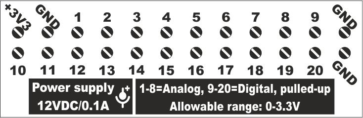 |
|||||||
| 8R2S1A | A | 12VDC (DC Jack) |
8 | 5A/240VAC 20A/14VDC |
2x [3xNO+1xSPDT] (2 buses x 4 relays) |
- | 2 | 1 | 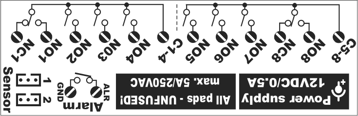 |
||||||
| 6R8A | D | 12VDC (DC Jack +Terminals) |
6 | 5A/240VAC 20A/14VDC |
3xNO+3xSPDT | 8 | 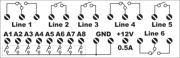 |
||||||||
| 4RU2S1A | D | 12VDC (DC Jack) |
4 | 7A 160VDC/110VAC |
3xNC + 1xSPDT | - | max. 160VDC /110VAC |
2 | 1 | 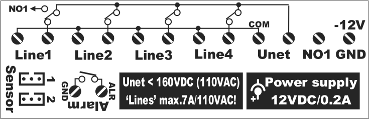 |
|||||
| 4R4S1A 4R4S1A WiFi |
A | 12VDC (DC Jack) |
4 | 7A /240VAC 7A /28VDC 12A /12VDC |
4xSPDT | 4 | 1 | 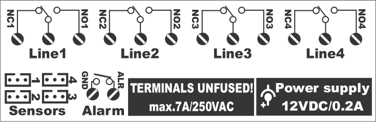 |
|||||||
| 2RU2S1A1P | D | 12VDC (DC Jack) <160VDC/110VAC (Terminals) |
2 | 7A 160VDC/110VAC 7A /28VDC 12A /12VDC |
2xSPDT | max. 160VDC /110VAC |
2 | 1 | 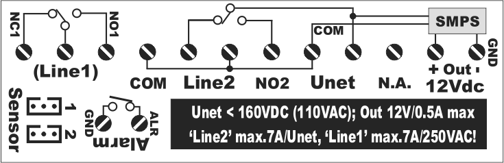 |
||||||
| 2R2S1A | D | 12VDC (DC Jack) |
2 | 7A /240VAC 7A /28VDC 12A /12VDC |
2xSPDT | 2 | 1 | 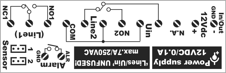 |
|||||||
| 2R4A | D | 12VDC (DC Jack +Terminals) |
2 | 7A /240VAC 7A /28VDC 12A /12VDC |
2xSPDT | 4 | 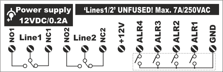 |
||||||||
| B | 12VDC (DC Jack) |
2 | 7A /240VAC 7A /28VDC 12A /12VDC |
2xSPDT | 2 | 2 | 4 |  |
|||||||
| Design | Enclosure specifications |
Power supply | Total number of relay channels |
Relay channels load specification |
Relay channels on common bus |
Idividual relay channels |
Line voltage measurement (< 160VDC/110VAC for PoE) |
Direct power supply of device from Line voltage (<160VDC/110VAC) |
Inputs for external sensors: TDS300 HDS300 VDS300 |
Alarm input (dry contact) |
Pulse counter inputs (for watt-hour, gas/water meters ...) |
0-10V Inputs/Outputs |
Back panel diagram | ||
| "Stock availability type" legend: A - always in stock; B - small quantities in stock; C - not kept in stock (can be manufactured on user request, MOQ=60pcs); D - discontinued | |||||||||||||||
Select your language

NetControl - reliability and flexibility
Born and raised in the ISP networks of Bulgaria

100% own design
Full control over software and hardware
